It is a safety system in automobiles. It prevents the wheels from locking while braking. The purpose of this is to allow the driver to maintain steering control under heavy braking and, in some situations, to shorten braking distances (by allowing the driver to hit the brake fully without skidding or loss of control).
How Do Wheels Lock?
During braking, wheels lock if the brake force applied is more than the friction between the road and tyre. This often happens in a panic braking situation, especially on a slippery road. When the front wheels lock, the vehicle slides in direction of motion. When the rear wheels locks, the vehicle swings around. It is impossible to steer around an obstacle with wheels locked. Locked wheels can thus result in accident. Skidding also reduce tyre life.
What Does ABS Do?
The system detects when the wheels are about to lock and momentarily release the pressure on locking wheel. The brakes are reapplied as soon as the wheels have recovered.
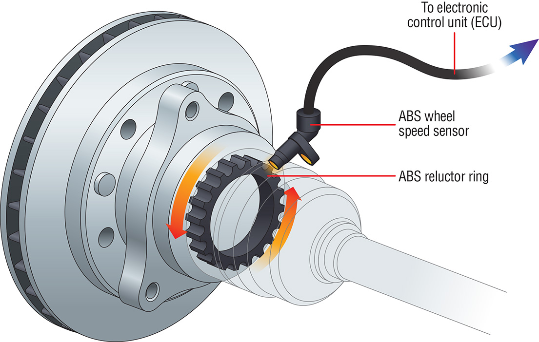
A toothed wheel (pole wheel) is fitted to the rotating wheel hub. A magnetic sensor mounted on each wheel in close proximity to the teeth, generates electrical pulses when the pole wheel rotates. The rate at which the pulses are generated (frequency) is a measure of wheel speed. This signal is read by electronic control unit (ECU).
When a wheel is locked, the ECU sends an electrical signal to the modulator valve solenoid, which release pressure from the brake chamber. When the wheel recovers sufficiently, the brake pressure is reapplied again by the switch off signal to the modulator valve.
The modulator valve has an addition 'hold' state which maintains pressure. In break in the chamber, thus optimizing the braking process. The cycling of modulator valve (5 to 6 times per second) is continued till the vehicle comes to a controlled stop.
With ABS, the vehicle remains completely stable even when the driver continues to press the brake pedal during braking, thus avoiding accidents.
Components:
The anti-lock braking system consists of following components.
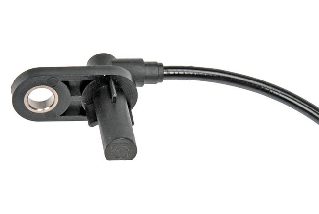
Wheel Speed Sensor
The wheel speed sensor consists of a permanent magnet and coil assembly. It generates electrical pulses when the pole wheel rotates. The rate at which the pulses are generated is a measure of wheel speed. The voltage induced increases with the speed of rotation of the wheel and reduces with increasing gap between the pole wheel and the sensor.
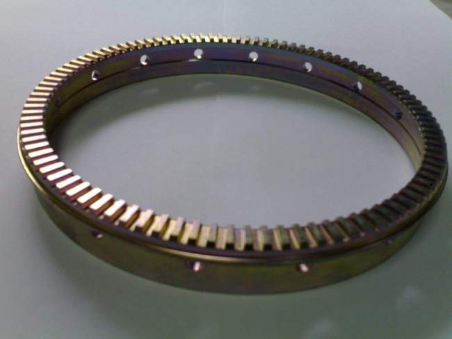
Pole Wheel
Pole Wheel is a toothed wheel made of ferrous material. It normally has teeth on the face. In some cases where it is not possible to install the sensor parallel to the axle, the pole wheels are designed with teeth on periphery. The pole wheel fitted on standard 9-20, 10-20 tires has normally 100 evenly spaced teeth. 80 evenly spaced teeth pole wheels are used for the vehicles having the Tyre diameter less than 9 mm.
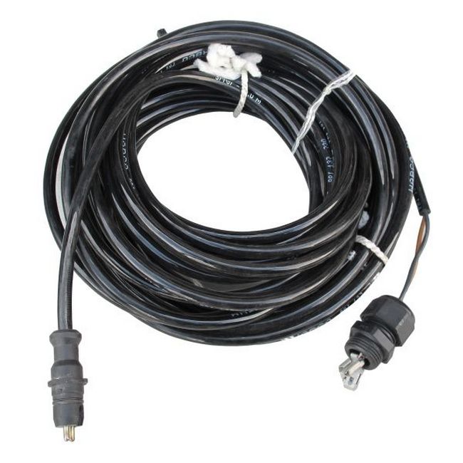
Sensor Extension Cable
The sensor extension cable is a two core cable which connects the wheel speed sensor to the Electronic Control Unit. The inner core sheathing is of EPDM rubber and the outer sheathing is polyurethane which provide abrasion resistance to the cable. The cable has a module plug with two pins is connected to the control assembly. The cable has two cores-brown and black in colour.
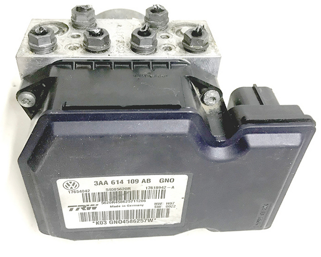
Electronic Control Unit
The ECU is the core component of the ABS system. Wheel speed sensor signal are the input to the Electronic Control Unit. The ECU computes wheel speeds, wheel deceleration and acceleration. If any wheel tends to lock, the ECU actuates the corresponding Modulator valve to prevent wheel lock. The ECU is normally mounted in driver's cabin.
The ECU consists of 7 major circuits,
- Input circuit
- Master circuit
- Slave circuit
- Driver circuit
- Feedback circuit
- Power supply circuit
- Fail safe circuit
The functions of ECU,
- It receives wheel speed signal from the sensor. The wheel speed signals are processed and appropriate output signals are sent to the modular valves in the event of a wheel lock.
- It continuously monitors the status and operation of ABS components and wiring.
- It alerts the driver in the event of occurrence of any electrical fault in the ABS system by actuating a warning lamp.
- It disconnects the exhaust brakes during ABS operations.
- It enables the service technician to read the faults in the system either through a diagnostic controller or a blink code lamp.
Modulator Valve Cable
The Modulator valve cable has thee cores. There are two solenoid interface lines and a common ground line. The inner core sheathing is of EPDM type and the outer sheathing is polyurethane which provide abrasion resistance to the cable.
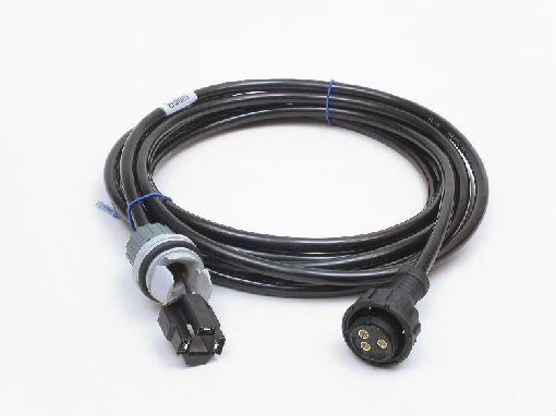
The cable has a three pin moulded socket connected to the modulator valve solenoid at one and an interlock connector with locking feature at the other end. The cores are brown, blue and green.
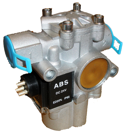
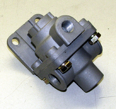
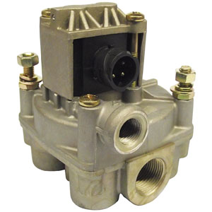
Modulator Valve
ABS Modulator valve regulate the air pressure to the brake chamber during ABS action. During normal braking it allows air to flow directly from inlet to delivery. Modulator valve cannot automatically apply the brakes, or increase the brake application pressure above the level applied by the driver through the dual brake valve.
There is an inlet port, Delivery port and Exhaust passage.
- The inlet port is connected to the delivery of quick release valve or relay valve.
- The delivery port is connected to the brake chamber.
- The exhaust passage vents air from the brake chambers.
The modulator valve has two solenoids. By energizing the solenoids, the modular valve can be switched to any of the following modes.
- Pressure
- Pressure hold
- Pressure release
Quick Release Valve
Quick release valve are fitted in air braking system to release the air from the brake chamber quickly after release of brake pedal. This prevents delay in brake release due to long piping runs or multiples of brake chamber being exhausted through the brake valve.
Relay Valve
Relay valve provides a means of admitting and releasing air to and from brake chamber quickly, in accordance with the signal pressure from the delivery of the dual brake valve. Air from the reservoir passes through the valve into the brake chamber. The pressure applied to the brake is equal to the signal pressure from the dual brake valve. When the brake pedal is released the signal pressure is released. The pressure in the brake chamber is released directly through the exhaust port of the relay valve.
Warning Lamp
Vehicle are fitted with an ABS warning lamp. It is a LED indicator lamp amber in color and lights up when the system has detected any electrical fault. ABS warning lamp is located on the instrument panel in form of a driver.
Blink Code Lamp
This lamp is green in color and is used to indicate the stored faults in the system to the service technician on operating a blink code switch. The nature of fault in the system can be diagnosed by the number of flashes.
Off Highway Switch
This is an optional switch in front of the driver which can be switched ON when the vehicle is operating off highway. In this mode, ABS control will; allow higher wheel slip to achieve shorter stopping distance than with normal ABS control.
Blink Code Switch
A momentary switch that grounds the ABS Indicator Lamp output is used to place the ECU into the diagnostic blink code mode and is typically located on the vehicle's dash panel.